Friday 28 October 2016
Wednesday 26 October 2016
HAVE YOU EVER TASTED AN ELECTRIC SHOCK ?
WHAT IS ELECTRICITY?
HAVE YOU TASTED AN ELECTRIC SHOCK? DO YOU KNOW WHY DO WE GET ELECTRIC SHOCK?
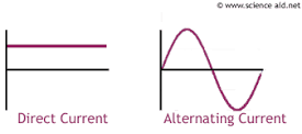
We are all aware of the word electricity or I should just say that we are all very very familiar with electricity. Of course we all know about Tesla and Edison and their fight between the forms of electricity i.e AC and DC.
Well there's a wide range of use for these forms of electricity. Electricity is being used in almost every possible way. Both the forms, AC as well as DC have a variety of uses like, for example AC is being used in almost all electrical and industrial appliances. On the other hand, DC or Direct Current is being used in almost all electronic devices. (ELECTRONIC DEVICES ARE DEVICES WHICH USE SEMICONDUCTOR CHIPS FOR THEIR BASIC CONSTRUCTION).
It is needless to give you the information about AC and DC and their uses and properties as the name itself suggests the meaning. Also there are great bloggers and professors who've already informed you about the two. So this is not my job, my job is to give you something that you don't know.
In fact I would provide you with something more interesting.
HAVE YOU EVER BEEN EXPOSED TO AN ELECTRIC SHOCK?
Okay now this is a senseless question, of course we all have experienced shock.
CAN YOU GUESS WHY?
DID YOU EVER WONDER WHY DO YOU GET A SHOCK EVERYTIME YOU TOUCH A LIVE WIRE (Bacically the red one) OR A NEUTRAL WIRE (Basically the black or yellow one), BUT THATS NOT THE CASE WITH THE WIRES OF BATTERY OR CELL, BASICALLY ANY DC VOLTAGE SOURCE ?
Well many of you won't know or perhaps you might know but you you never dragged you attention towards the reason!!
And did you ever notice that while you place both the wires of the DC source in your mouth you experience a mild current no your tongue? Did't you try? Well then give it a try before reading this further(remember that voltage should be less than 9 volt or else you would get a greater shock).
CAN YOU GUESS THE REASON?
Well many of you think that the primary reason is the voltage level or level of energy from the sources. Well but that reason is valid only for the extent of the shock you experience while subjected to AC or DC.
But thats not the reason for getting a shock in case of touching any wire of an AC source and not getting in case of touching any terminal or wire of the DC source.
INTERESTED IN ELECTRONICS??
Electronics Project spares with breadboard, 30 circuits eBook CD + videos
 |
| CLICK HERE |
Well here is the reason. When you are subjected to only one terminal of the DC voltage source, you are experiencing only the voltage of the source and not the current. Also you should know that you are getting energy only when you touch the positive terminal, during the touch of the negative terminal you are not at all experiencing any voltage or energy since the voltage the negative terminal has is almost zero or negligible. This difference is known as the Potential Difference, which is necessary condition for electric current flow.
And when you touch both the terminals together to your saliva wet tongue [ which is capable of experiencing the mildest is electric current ]
you complete the circuit and hence completing the Ohm's Law (which says that we produce current from voltage on applying resistance in the flowing path of the voltage.). Here the resistance offered is the tongue. So the conclusion is that its the current that gives us the shock and not the voltage.
By now I presume that you've understood why do we get the shock in case of AC even when we touch only one of the two terminals of the AC source.
NO!
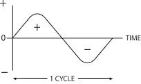
Okay then here's the reason, AC is a pulsating DC or a current that is alternating i.e it keeps on changing its polarity at any instance of time.
Any of the two terminals of the AC source has both positive as well as negative polarity which changes from one polarity to other at the gap of a fraction of a millisecond which is practically zero.
So here when you touch only one terminal the circuit gets completed and you provide the resistance by the touch which gives the experience of shock.
let me know how was your experience and your feedback about this article in the comment section..
any correction or advice or request is heartily welcomed.
Saturday 22 October 2016
HOW TO MAKE A PHOTO SENSOR USING IC7408
IC 7408

IC 7408 IS A LOGICAL AND GATE WHICH COMPRISES OF 14 PINS NAMED 1,2,3...SO ON FROM THE SIDE THAT HASA SPOT OR A DOT. YOU CAN SEE IN THE DIAGRAM.
THE PINS 1 AND 2 ARE THE INPUTS TO THE AND GATE NO.1 AND PIN 3 IS THEIR OUTPUT.
SIMILARLY THE OTHER AND GATES NO.2, 3 AND 4 HAVE PINS (4,5), (8,9), AND (11,12) AS THEIR INPUTS RESPECTIVELY. ALSO PINS 6,10 AND 13 ARE THE OUTPUTS TO THE GATES 2,3 AND 4 RESPECTIVELY.
THE IMPORTANT PART IS TO NOTICE THAT PIN 7 IS THE GROUND TERMINAL OR WE CAN SAY IT IS THE ZERO VOLTAGE SOURCE FROM THE TERMINAL OF THE VOLTAGE SOURCE. PIN NO. 14 IS THE POSITIVE TERMINAL TO THE VOLTAGE SOURCE.
HERE IS THE PIN DIAGRAM OF THE IC 7408
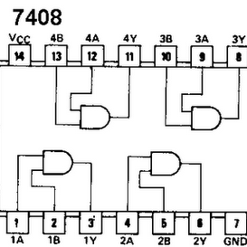
THE LETTERS A, B AND Y FROM THE DIAGRAM INDICATE THE INPUTS AND THE OUTPUTS OF THE CIRCUIT.
SO WHILE CONNECTING THE COMPONENTS TO THE CIRCUIT IT IS NECESSARY TO CONNECT THE GROUND AND THE POSITIVE VCC TO THE TERMINALS OF THE VOLTAGE SOURCE.
SO BY USING THE IC7408 I HAVE DESIGNED A SIMPLEST CIRCUIT THAT WORKS AS A DARK SENSOR OR WE MAY CALL A PHOTO SENSOR OR LIGHT SENSOR. USING THE IC AND THE LDR, (WHICH IS THE LIGHT DEPENDENT RESISTOR) WE CAN EASILY MAKE A SWITCH THAT FUNCTIONS AS AN ALTERNATING SWITCH.
WE NEED TO HAVE LOOK AT THE TRUTH TABLE OF THE AND GATE

AS WE CAN SEE FROM THE IMAGE WHEN THE INPUTS ARE LOW i.e 0-0 THE OUTPUT REMAINS LOW i.e 0. AND WHEN THE INPUT REMAINS HIGH OR 1-1 THE OUTPUT REMAINS HIGH. ALSO TO BE NOTED WHEN THE INPUTS ARE 1-0 OR 0-1 THE OUTPUT IS LOW OR 0.
SO HERE'S THE CIRCUIT DIAGRAM THAT ALLOWS YOU TO MAKE USE OF THIS PROPERTY IN AN INCREDIBLY CREATIVE WAY.
REFER THE IMAGE BELOW..

SO HERE'S THE CIRCUIT DIAGRAM THAT I'VE DESIGNED. AS YOU CAN SEE WE'RE USING AN IC 7408, A LDR AND A BUZZER. ALSO WE ARE USING A BREADBOARD, SOME SOLID WIRES AND A VOLTAGE SOURCE. SEE ITS THAT SIMPLE!
YOU CAN ALSO MAKE THE SIMPLE CIRCUIT ARRANGEMENT ON A PRINTED CIRCUIT BOARD (PCB) IF YOU HAVE A HANDS ON EXPERIENCE WITH SOLDERING EQUIPMENT.
ANYWAYS FOR A SIMPLER UNDERSTANDING WE BUILD THE CIRCUIT ON A BREAD BOARD.
SO FIRST WE NEED TO UNDERSTAND THE IC CONFIGURATION FROM THE DIAGRAM. ACCORDING TO THE CIRCUIT DIAGRAM THE PIN NO. 14 IS FOR POSITIVE VCC. AND THE PIN NO. 7 IS FOR ZERO VCC OR THE GROUND (WHICH IS NOTHING BUT THE NEGATIVE SUPPLY OF THE VOLTAGE SOURCE). PINS 1 AND 2 SERVE AS THE INPUT AND THE PIN 3 GIVES THE OUTPUT FOR THE AND GATE 1.
SINCE THE POWER SUPPLY IS ALREADY COMPLETE TO THE CIRCUIT AS IN FROM PINS 14 AND 7, SO EVEN IF WE LEAVE THE TWO INPUTS OPEN THE CIRCUIT WILL CONSIDER IT AS CLOSED LOOP. AND THE IC WILL PRESUME IT BE A POSITIVE SUPPLY AT THE TERMINALS 1 AND 2 . SO WE'RE GOING TO CONNECT BOTH THE TERMINAL TOGETHER
AND MAKE IT A SINGLE TERMINAL, AND THEN CONNECT IT TO ONE END OF THE LDR.
THE LDR WE USE IS THE PHOTO SENSOR. THE OTHER END OF THE PHOTO SENSOR IT CONNECTED TO THE GROUND, AS WE CAN SEE FROM THE DIAGRAM.
THE OUTPUT PIN 3 IS CONNECTED TO ONE OF THE END OF THE BUZZER AND THE OTHER END OF THE BUZZER IS CONNECTED TO THE GROUND.
NOW WHEN WE SUPPLY THE VOLTAGE FROM THE SOURCE
, WE COMPLETE THE CIRCUIT, BUT SINCE WE ARE USING AN LDR IT WORKS AS SWITCH WHICH COMES INTO ACTION WHEN LIGHT FALLS ONTO IT. SINCE ABSORBING OF LIGHT REDUCES ITS RESISTANCE TO AN EXTREMELY LOW LEVEL WE CAN USE IT AS A SWITCH.
NOW WHEN WE CONNECT THE VOLTAGE SOURCE THE CIRCUIT GETS COMPLETED.
WE CAN SEE THAT WHEN LIGHT FALLS ON THE LDR THE RESISTANCE VALUE GETS LOW WHICH MAKES THE SWITCH CLOSE. HERE THE SWITCH IS CLOSED AND THE INPUTS GET GROUNDED. AND UNTIL THE SYSTEM IS EXPOSED TO LIGHT THE CIRCUIT REMAINS IN A SWITCHOFF STATE. AS SOON AS WE CUT THE PASSAGE OF LIGHT TO THE LDR THE CIRCUIT BECOMES OPEN AND THE INPUT GETS DISCONNECTED FROM THE GROUND STATE COMPLETING THE CIRCUIT WITH POSITIVE INPUT AND YOU'LL GET A RESULT..
GIVE IT A TRY...
APPLICATIONS OF THIS CIRCUIT..
APPLICATION OF THIS CIRCUIT CAN BE MADE IN DIFFERENT SECTORS SUCH AS FOR SECURITY PURPOSES, AUTOMATIC STREET LIGHTS, SWITCHES,ETC..
OR SIMPLY CONNECT A CLICK CAMERA OT IT AND FACE IT TO THE PASSAGE OF THE LIGHT TO SEE WHO TRESS PASSES YOUR PRIVATE PLACES...
ENJOY!!
Subscribe to:
Posts (Atom)